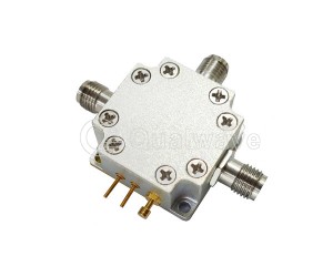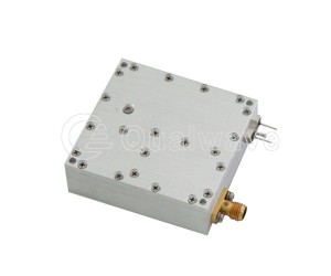
Features:
- Low VSWR
 +86-28-6115-4929
  sales@qualwave.com





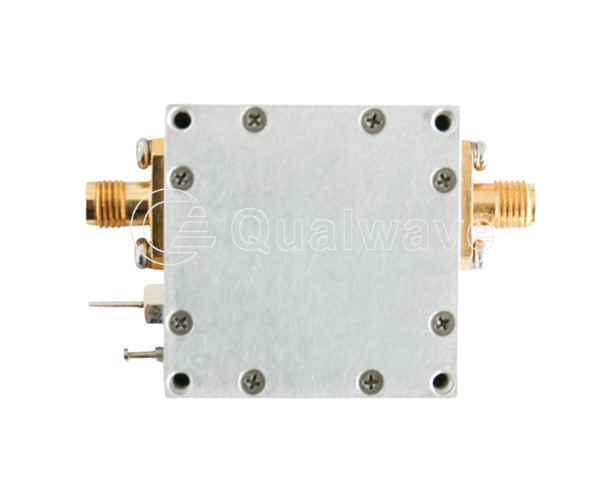
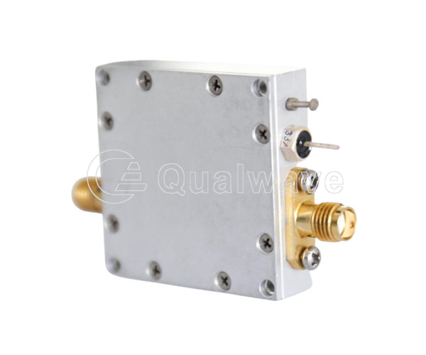
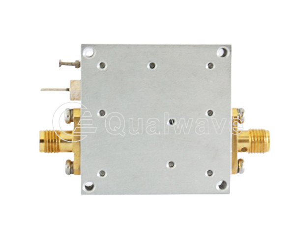
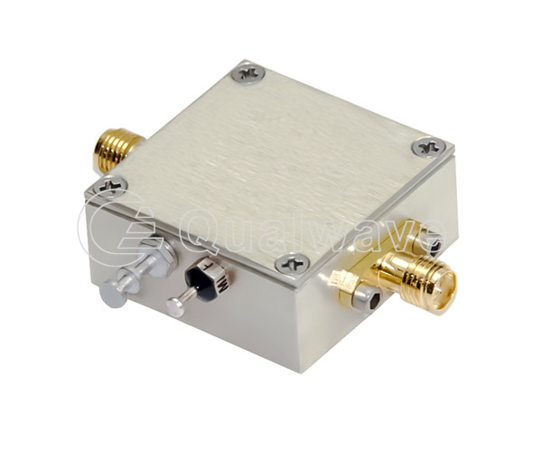
A waveguide frequency divider is an electronic component that divides the input signal frequency by a constant factor to produce an output signal with a lower frequency. It plays an important role in signal processing and frequency control.
1.Millimeter wave frequency divider can divide the frequency of the input signal into a lower frequency, usually the input frequency can be divided by a multiple of 2, 3, 4 and so on.
2.The mm wave frequency divider is usually implemented using the frequency divider circuit, frequency divider chip or counter.
3.Radio frequency frequency divider can be applied to digital logic circuit or clock control circuit.
1.Signal processing optimization: the frequency of the input signal is reduced or divided into multiple frequency components. This is useful for applications that require the processing and analysis of signals in a specific frequency range.
2.Frequency control and timing generation: By dividing the frequency of the input signal by a fixed multiple, the microwave frequency divider can produce a lower frequency output signal.
3.Communication and radio: high-frequency signals are divided into lower frequencies to adapt to specific communication standards and protocol requirements.
4.Signal spectrum analysis: By dividing the input signal into a lower frequency range, it is easier to perform spectrum analysis and frequency domain processing of the signal.
The Qualwave company provides 0.1~30GHz high frequency frequency divider, with pre-divider 2 frequency, 6 frequency, 8 frequency, 10 frequency, 32 frequency, and 256 frequency six configurations, products with ultra-wideband coverage, small current and small size, high input sensitivity and low phase noise characteristics, widely used in laboratory systems, optical fiber radio frequency, high frequency communication, microwave instruments and electronic warfare radar systems. Welcome customers to inquire, we will provide you with professional service.

| 2 Frequency Dividers | |||||||||
|---|---|---|---|---|---|---|---|---|---|
| Part Number | Input Frequency (GHz) | Output Frequency (GHz) | Output Power (dBm Min.) | Divide Ratio | Harmonic (dBc Max.) | Spurious (dBc Max.) | Voltage (V) | Current (A) | LeadTime (Weeks) |
| QFD2-100 | 0.1 | 0.05 | 5~8 | 2 | -60 | -75 | 12 | 0.15 | 4~6 |
| QFD2-500-26500 | 0.5~26.5 | 0.25~13.25 | -3 | 2 | - | - | 12 | 0.1 | 4~6 |
| 6 Frequency Dividers | |||||||||
| Part Number | Input Frequency (GHz) | Output Frequency (GHz) | Output Power (dBm Min.) | Divide Ratio | Harmonic (dBc Max.) | Spurious (dBc Max.) | Voltage (V) | Current (A) | LeadTime (Weeks) |
| QFD6-0.001 | - | 1K | - | 6 | - | - | +5 | - | 4~6 |
| 8 Frequency Dividers | |||||||||
| Part Number | Input Frequency (GHz) | Output Frequency (GHz) | Output Power (dBm Min.) | Divide Ratio | Harmonic (dBc Max.) | Spurious (dBc Max.) | Voltage (V) | Current (A) | LeadTime (Weeks) |
| QFD8-80 | 0.08 | 0.01 | 10 | 8 | -30 | -75 | +8~+12 | 0.16 | 4~6 |
| 10 Frequency Dividers | |||||||||
| Part Number | Input Frequency (GHz) | Output Frequency (GHz) | Output Power (dBm Min.) | Divide Ratio | Harmonic (dBc Max.) | Spurious (dBc Max.) | Voltage (V) | Current (A) | LeadTime (Weeks) |
| QFD10-900-1100 | 0.9~1.1 | 0.09~0.11 | 5~8 | 10 | -30 | -75 | +12 | 0.2 | 4~6 |
| QFD10-1000 | 1 | 0.1 | 5~8 | 10 | -30 | -75 | +12 | 0.2 | 4~6 |
| QFD10-9900-10100 | 9.9~10.1 | 0.99~1.01 | 7~10 | 10 | - | - | +8 | 0.23 | 4~6 |
| 32 Frequency Dividers | |||||||||
| Part Number | Input Frequency (GHz) | Output Frequency (GHz) | Output Power (dBm Min.) | Divide Ratio | Harmonic (dBc Max.) | Spurious (dBc Max.) | Voltage (V) | Current (A) | LeadTime (Weeks) |
| QFD32-2856 | 2.856 | 0.08925 | 10±2 typ. | 32 | - | - | +12 | 0.3 | 4~6 |
| 256 Frequency Dividers | |||||||||
| Part Number | Input Frequency (GHz) | Output Frequency (GHz) | Output Power (dBm Min.) | Divide Ratio | Harmonic (dBc Max.) | Spurious (dBc Max.) | Voltage (V) | Current (A) | LeadTime (Weeks) |
| QFD256-300-30000 | 0.3~30 | - | 0~3 typ. | 256 | - | - | +8 | 0.3 | 4~6 |