Features:
- Low VSWR
 +86-28-6115-4929
  sales@qualwave.com


In radio frequency and microwave systems, the waveguide is the highest performance of the interconnection and passive components, mainly in the given frequency band to effectively transmit radio frequency signal energy, and the main structure of the waveguide is metal conductive materials, can handle extremely high power levels.
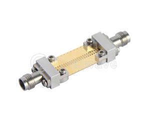
As the name suggests, the waveguide straight sections are directly connected without changing its signal transmission direction, and the length can be customized according to the application scenario, ranging from a few centimeters to a few meters.
The design and manufacturing of waveguide straight sections need to consider various factors, such as operating frequency, waveguide size, material selection, processing technology, etc. Common types of waveguide transition devices include transitions from rectangular waveguides to circular waveguides, transitions between rectangular waveguides of different sizes, and transitions from waveguides to coaxial lines.
1. As a transmission line, the RF waveguides work by transferring energy from one place to another, achieving efficient transmission by reducing the loss in the energy transmission process. The hollow metal structure of the waveguide can greatly reduce the loss in the energy transmission process.
2. In contrast to the antenna, the energy is not radiated into the entire space in the waveguide, but is bound inside the waveguide, and only energy above a specific cutoff frequency can be transmitted through the microwave waveguides.
Applications of radio frequency waveguides are not limited to communications and radar systems. For example, in hyperlens imaging, cascaded arrays of straight waveguides and curved waveguides are used to simulate positive and negative refractive index materials to achieve sub-wavelength self-imaging. This technique is of great significance in imaging technology and photon integration, especially in the realization of precise regulation of light field at sub-wavelength scale.
Qualwave supplies waveguide straight sections cover the frequency range up to 91.9GHz, as well as customized waveguide straight sections according to customers requirements. Welcome customers to inquire more product details.

Part Number |
RF Frequency(GHz, Min.)  |
RF Frequency(GHz, Max.) |
Insertion Loss(dB, Max.) |
VSWR(Max.) |
Waveguide Size |
Flange |
Lead Time(Weeks) |
|---|---|---|---|---|---|---|---|
| QWSS-12 | 60.5 | 91.9 | 0.5 | 1.1 | WR-12 (BJ740) | UG387/U | 2~4 |
| QWSS-15 | 49.8 | 75.8 | 0.5 | 1.1 | WR-15 (BJ620) | UG385/U | 2~4 |
| QWSS-28 | 26.5 | 40 | 1dB/m | 1.1 | WR-28 (BJ320) | FBP320 | 2~4 |
| QWSS-34 | 21.7 | 33 | 0.1 | 1.08 | WR-34 (BJ260) | FBP260 | 2~4 |
| QWSS-42 | 18 | 26.5 | 0.08 | 1.05 | WR-42 (BJ220) | FBP220 | 2~4 |
| QWSS-62 | 11.9 | 18 | 0.05 | 1.05 | WR-62 (BJ140) | FBP140 | 2~4 |
| QWSS-75 | 9.84 | 15 | 0.25dB/m | 1.05 | WR-75 (BJ120) | FBP120 | 2~4 |
| QWSS-90 | 8.2 | 12.5 | 0.1 | 1.05 | WR-90 (BJ100) | FBP100 | 2~4 |
| QWSS-187 | 3.94 | 5.99 | 0.2 | 1.2 | WR-187 (BJ48) | FAM48, FDM48 | 2~4 |
| QWSS-430 | 1.72 | 2.61 | 0.1 | 1.1 | WR-430 (BJ22) | FDP22 | 2~4 |
| QWSS-650 | 1.13 | 1.73 | - | 1.1 | WR-650 (BJ14) | FDP14 | 2~4 |
| QWSS-D180 | 18 | 40 | 1.2dB/m | 1.1 | WRD-180 | FPWRD180 | 2~4 |
| QWSS-D750 | 7.5 | 18 | 0.4 | 1.15 | WRD-750 | FPWRD750 | 2~4 |
| QWSS-D750-100-A-8-H | 7.5 | 18 | 0.1 | 1.1 | WRD-750 | FPWRD750 | 2~4 |
| QWSS-D350 | 3.5 | 8.2 | 0.4 | 1.15 | WRD-350 | FPWRD350 | 2~4 |
| QWSS-D350-100-A-8-H | 3.5 | 8.2 | 0.15 | 1.1 | WRD-350 | FPWRD350 | 2~4 |