Features:
- Broadband
- Small Size
- Low Insertion Loss
 +86-28-6115-4929
  sales@qualwave.com


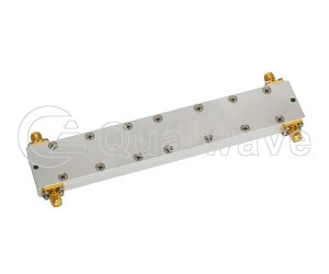
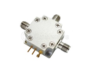
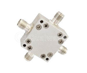
Waveguide power dividers and magic tees are important components in microwave and RF engineering. They are used to distribute power between multiple paths or combine signals in waveguide systems. A waveguide power divider is a device used to distribute input signals to multiple output ports, widely used in microwave and radio frequency (RF) engineering. As a microwave component, the magic T is also known as the E-H planar tee. The reason why it is named "Magic T" is that it can not only distribute the energy entering the E-plane port and H-plane port between two collinear ports on the same line, but also isolate the E-plane port and H-plane port from these two collinear ports at the same time.
1. Unlike other power dividers or couplers, the E-plane port and H-plane port of the Magic T have relatively independent functions.
2. The H-plane port (also known as the summation port) is a in-phase port for two collinear ports, while the E-plane port is a 180 degree reverse port for these two ports.
3. The function of Magic T has symmetry, which distributes the energy entering the collinear port between the E-plane port and the H-plane port. From this, it can be seen that Magic T divides the signals entering the collinear port simultaneously, adds the segmented signals at the H-plane port, and subtracts the segmented signals at the E-plane port.
The above functions can only be fully realized under theoretical basis or ideal conditions. In practical operation, magic T with different matching degree, balance degree, and isolation degree has various limitations.
The 'demonic nature' of MoT also lies in its wide range of applications. Can be used as an impedance measurement tool, duplexer, mixer.
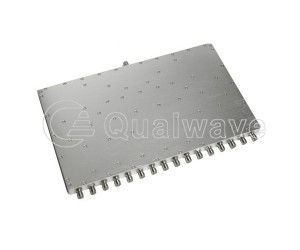
Qualwave supplies High Power Waveguide Power Dividers & Magic Tees at frequencies from 4.4 to 112GHz, and the power is up to 11000W. Our Waveguide Power Dividers & Magic Tees are widely used in many areas.

| 2-Way Waveguide Power Dividers & Magic Tees | |||||||||||
|---|---|---|---|---|---|---|---|---|---|---|---|
| Part Number | Frequency (GHz) | Power as Divider (W) | Power as Combiner (W) | IL (dB, Max.) |
Isolation (dB, Min.) |
Amplitude Balance (dB, Max.) |
Phase Balance (°, Max.) |
VSWR (Max.) |
Waveguide Size | Flange | Lead Time (Weeks) |
| QWPD2-13750-14500-3K2-75 | 13.75~14.5 | 3200 | 3200 | 0.3 | 20 | - | ±3 | 1.3 | WR-75 (BJ120) | FBP120 | 2~3 |
| QWPD2-17300-18100-2K-51 | 17.3~18.1 | 2000 | 2000 | 0.1 | - | 0.2 | - | 1.2 | WR-51 (BJ180) | - | 2~3 |
| QWPD2-17300-18100-3K-51 | 17.3~18.1 | 3000 | 3000 | 0.2 | - | - | - | 1.2 | WR-51 (BJ180) | - | 2~3 |
| QWPD2-18000-26500-K15-42 | 18~26.5 | 150 | 150 | 0.25 | - | - | ±3 | 1.15 | WR-42 (BJ220) | FBP220 | 2~3 |
| QWPD2-26500-40000-K5-28 | 26.5~40 | 500 | 500 | 0.25 | - | - | ±3 | 1.15 | WR-28 (BJ320) | FBP320 | 2~3 |
| QWPD2-40000-46000-50-22 | 40~46 | 50 | 50 | 0.3 | 20 | - | ±3 | 1.3 | WR-22 (BJ400) | FUGP400 | 2~3 |
| QWPD2-40000-50000-K3-19 | 40~50 | 300 | 300 | 0.5 | 15 | - | ±5 | 1.5 | WR-19 (BJ500) | FUGP500 | 2~3 |
| QWPD2-50000-61000-K4-15 | 50~61 | 400 | 400 | 0.4 | - | ±0.3 | ±5 | 1.7 | WR-15 (BJ620) | FUGP620 | 2~3 |
| QWPD2-50000-75000-K15-15 | 50~75 | 150 | 150 | 0.5 | - | - | ±5 | 1.3 | WR-15 (BJ620) | FUGP620 | 2~3 |
| QWPD2-60000-90000-10-12 | 60~90 | 10 | 10 | 0.5 | 20 | - | ±5 | 1.25 | WR-12 (BJ740) | FUGP740 | 2~3 |
| QWPD2-73800-11200-K3-10 | 73.8~112 | 300 | 300 | 0.5 | - | - | ±5 | 1.3 | WR-10 (BJ900) | FUGP900 | 2~3 |
| QWPD2-74000-110000-K3-10 | 74~110 | 300 | 300 | 0.4 | - | - | ±5 | 1.3 | WR-10 (BJ900) | FUGP900 | 2~3 |
| 3-Way Waveguide Power Dividers | |||||||||||
| Part Number | Frequency (GHz) | Power as Divider (W) | Power as Combiner (W) | IL (dB, Max.) |
Isolation (dB, Min.) |
Amplitude Balance (dB, Max.) |
Phase Balance (°, Max.) |
VSWR (Max.) |
Waveguide Size | Flange | Lead Time (Weeks) |
| QWPD3-17300-18100-K2-51 | 17.3~18.1 | 200 | 200 | 0.5 | - | 0.3 | 6 | 1.5 | WR-51 (BJ180) | - | 2~3 |
| QWPD3-40000-50000-K3-19 | 40~50 | 300 | 300 | 0.8 | - | - | 36 | 1.3 | WR-19 (BJ500) | FUGP500 | 2~3 |
| QWPD3-40000-50000-1K-22 | 40~50 | 1000 | 1000 | 0.3 | - | ±0.3 | ±15 | 1.3 | WR-22 (BJ400) | FUGP400 | 2~3 |
| 4-Way Waveguide Power Dividers | |||||||||||
| Part Number | Frequency (GHz) | Power as Divider (W) | Power as Combiner (W) | IL (dB, Max.) |
Isolation (dB, Min.) |
Amplitude Balance (dB, Max.) |
Phase Balance (°, Max.) |
VSWR (Max.) |
Waveguide Size | Flange | Lead Time (Weeks) |
| QWPD4-4400-5000-1K6-187 | 4.4~5 | 1600 | 1600 | 0.8 | 15 | 0.4 | 5 | 1.6 | WR-187 (BJ48) | - | 2~3 |
| QWPD4-5850-6650-K5-137 | 5.85~6.65 | 500 | 500 | 0.4 | - | 0.3 | 5 | 1.4 | WR-137 (BJ70) | - | 2~3 |
| QWPD4-13750-14500-1K6-75 | 13.75~14.5 | 1600 | 1600 | 0.3 | - | - | ±3 | 1.3 | WR-75 (BJ120) | FBP120 | 2~3 |
| QWPD4-18000-40000-K1-D180 | 18~40 | 100 | 100 | 0.8 | - | ±0.3 | ±5 | 1.5 | WRD-180 | FPWRD180 | 2~3 |
| QWPD4-18000-40000-1K-D180 | 18~40 | 1000 | 1000 | 0.5 | - | ±0.3 | ±5 | 1.35 | WRD-180 | FPWRD180 | 2~3 |
| QWPD4-27000-31000-2K-34 | 27~31 | 2000 | 2000 | 0.3 | - | - | ±3 | 1.3 | WR-34 (BJ260) | FBP260 | 2~3 |
| QWPD4-40000-50000-K1-22 | 40~50 | 100 | 100 | 0.35 | - | ±0.3 | ±15 | 1.3 | WR-22 (BJ400) | FUGP400 | 2~3 |
| QWPD4-50000-61000-20-15 | 50~61 | 20 | 20 | 0.6 | - | ±0.4 | ±8 | 1.7 | WR-15 (BJ620) | FUGP620 | 2~3 |
| 6-Way Waveguide Power Dividers | |||||||||||
| Part Number | Frequency (GHz) | Power as Divider (W) | Power as Combiner (W) | IL (dB, Max.) |
Isolation (dB, Min.) |
Amplitude Balance (dB, Max.) |
Phase Balance (°, Max.) |
VSWR (Max.) |
Waveguide Size | Flange | Lead Time (Weeks) |
| QWPD6-27000-31000-2K-34 | 27~31 | 2000 | 2000 | 0.3 | - | - | ±6 | 1.3 | WR-34 (BJ260) | FBP260 | 2~3 |
| 8-Way Waveguide Power Dividers | |||||||||||
| Part Number | Frequency (GHz) | Power as Divider (W) | Power as Combiner (W) | IL (dB, Max.) |
Isolation (dB, Min.) |
Amplitude Balance (dB, Max.) |
Phase Balance (°, Max.) |
VSWR (Max.) |
Waveguide Size | Flange | Lead Time (Weeks) |
| QWPD8-17700-26500-K2-42 | 17.7~26.5 | 200 | 200 | 0.5 | - | - | ±4 | 1.4 | WR-42 (BJ220) | FBP220 | 2~3 |
| QWPD8-27000-31000-2K-34 | 27~31 | 2000 | 2000 | 0.3 | - | - | ±5 | 1.3 | WR-34 (BJ260) | FBP260 | 2~3 |
| QWPD8-27500-31000-K2-28 | 27.5~31 | 200 | 200 | 0.4 | - | 0.3 | 6 | 1.6 | WR-28 (BJ320) | - | 2~3 |
| 16-Way Waveguide Power Dividers | |||||||||||
| Part Number | Frequency (GHz) | Power as Divider (W) | Power as Combiner (W) | IL (dB, Max.) |
Isolation (dB, Min.) |
Amplitude Balance (dB, Max.) |
Phase Balance (°, Max.) |
VSWR (Max.) |
Waveguide Size | Flange | Lead Time (Weeks) |
| QWPD16-8500-9500-11K-90 | 8.5~9.5 | 11000 | 11000 | 0.5 | - | - | ±5 | 1.3 | WR-90 (BJ100) | FBP100 | 2~3 |
| QWPD16-27000-31000-K5-28 | 27~31 | 500 | 500 | 0.3 | - | - | ±8 | 1.3 | WR-28 (BJ320) | FBP320 | 2~3 |