 +86-28-6115-4929


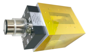
Waveguide switch is a critical component in microwave systems used to control signal paths, enabling switching or toggling signal transmission between different waveguide channels. Below is an introduction from both features and applications perspectives:
Characteristics:
1. Low insertion loss
Utilizes high-conductivity materials and precision structural design to ensure minimal signal loss, making it suitable for high-power applications.
2. High isolation
Isolation between ports can exceed 60 dB in the off state, effectively suppressing signal leakage and crosstalk.
3. Fast switching
Mechanical switches achieve millisecond-level switching, while electronic switches (ferrite or PIN diode-based) can reach microsecond-level speeds, ideal for dynamic systems.
4. High power handling
Waveguide structures can withstand kilowatt-level average power (e.g., radar applications), with superior high-voltage and high-temperature tolerance compared to coaxial switches.
5. Multiple drive options
Supports manual, electric, electromagnetic, or piezoelectric actuation to adapt to different scenarios (e.g., automated testing or harsh environments).
6. Wide bandwidth
Covers microwave frequency bands (e.g., X-band 8-12 GHz, Ka-band 26-40 GHz), with some designs supporting multi-band compatibility.
7. Stability & Reliability
Mechanical switches offer a lifespan exceeding 1 million cycles, electronic switches are wear-free, suitable for long-term use.
Applications:
1. Radar systems
Antenna beam switching (e.g., phased array radar), transmit/receive (T/R) channel switching to enhance multi-target tracking.
2. Communication systems
Polarization switching (horizontal/vertical) in satellite communications or routing signals to different frequency processing modules.
3. Test & Measurement
Rapid switching of devices under test (DUT) in automated test platforms, improving multi-port calibration efficiency (e.g., network analyzers).
4. Electronic warfare (EW)
Fast mode switching (transmit/receive) in jammers or selecting different frequency antennas to counter dynamic threats.
5. Medical equipment
Directing microwave energy in therapeutic devices (e.g., hyperthermia treatment) to avoid overheating non-target areas.
6. Aerospace & Defense
RF systems in aircraft (e.g., navigation antenna switching), requiring vibration-resistant and wide-temperature operation.
7. Scientific research
Routing microwave signals to different detection equipment in high-energy physics experiments (e.g., particle accelerators).
Qualwave Inc. provide waveguide switches with a frequency range of 1.72~110 GHz, covering waveguide sizes from WR-430 to WR-10, widely used in radar systems, communication equipment, and test & measurement fields. This article introduces a 1.72~2.61 GHz, WR-430 (BJ22) waveguide switch.
1. Electrical Characteristics
Frequency: 1.72~2.61GHz
Insertion Loss: 0.05dB max.
VSWR: 1.1 max.
Isolation: 80dB min.
Voltage: 27V±10%
Current: 3A max.
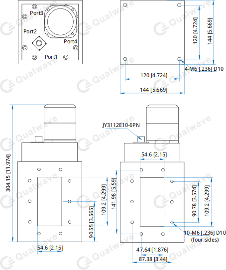
2. Mechanical Properties
Interface: WR-430 (BJ22)
Flange: FDP22
Control Interface: JY3112E10-6PN
Switching Time: 500mS
3. Environment
Operating Temperature: -40~+85℃
Non-operating Temperature: -50~+80℃
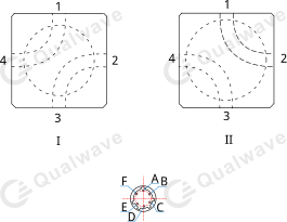
4. Driving Schematic Diagram
5. Outline Drawings
5. How To Order
QWSD-430-R2、QWSD-430-R2I
We believe that our competitive pricing and robust product line can greatly benefit your operations. Kindly reach out should you wish to ask any questions.
Post time: Jun-20-2025