 +86-28-6115-4929


Microwave frequency divider, also known as a power splitter, is a critical passive component in RF and microwave systems. Its core function is to accurately distribute an input microwave signal into multiple output ports in specific proportions (typically equal power), and conversely, it can also be used as a power combiner to synthesize multiple signals into one. It acts as a "traffic hub" in the microwave world, determining the efficient and precise distribution of signal energy, serving as the cornerstone for building complex modern communication and radar systems.
Key Features:
1. Low insertion loss: Utilizing precision transmission line design and high-performance dielectric materials, it minimizes signal power loss during distribution, ensuring stronger effective signals at the system output and significantly enhancing overall system efficiency and dynamic range.
2. High port isolation: The extremely high isolation between output ports effectively prevents signal crosstalk, avoiding harmful intermodulation distortion and ensuring independent, stable, and parallel operation of multi-channel systems. This is crucial for multi-carrier aggregation applications.
3. Excellent amplitude and phase consistency: Through meticulous symmetrical structure design and simulation optimization, it ensures highly consistent amplitude balance and phase linearity across all output channels. This feature is indispensable for advanced systems requiring high channel consistency, such as phased array radars, satellite communications, and beamforming networks.
4. High power handling capacity: Constructed with high-quality metal cavities and reliable internal conductor structures, it offers excellent heat dissipation and can withstand high average and peak power levels, fully meeting the stringent requirements of high-power applications such as radar, broadcast transmission, and industrial heating.
5. Excellent voltage standing wave rtio (VSWR): Both input and output ports achieve excellent VSWR, indicating superior impedance matching, effectively reducing signal reflection, maximizing energy transmission, and enhancing system stability.
Typical Applications:
1. Phased array radar systems: Serving as a core component at the front end of T/R modules, it provides power distribution and signal synthesis for a large number of antenna elements, enabling electronic beam scanning.
2. 5G/6G base stations (AAU): In antennas, it distributes RF signals to dozens or even hundreds of antenna elements, forming directional beams to enhance network capacity and coverage.
3. Satellite communication earth stations: Used for signal combining and splitting in uplink and downlink paths, supporting multi-band and multi-carrier simultaneous operation.
4. Test and measurement systems: As an accessory for vector network analyzers and other test equipment, it splits a signal source output into multiple paths for multi-port device testing or comparative testing.
5. Electronic countermeasure (ECM) systems: Used for multi-point signal distribution and interference synthesis, enhancing system effectiveness.
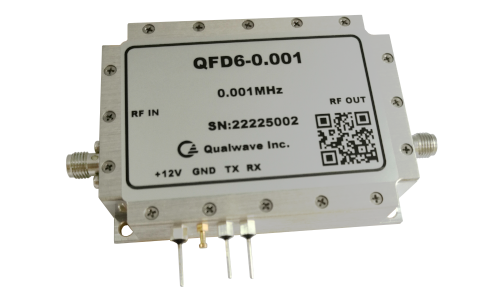
Qualwave Inc. provide various types of frequency divider in a wide range from 0.1GHz to 30GHz, widely used in multiple fields. This article introduces a variable frequency divider with a frequency of 0.001MHz.
1. Electrical Characteristics
Frequency: 0.001MHz max.
Divide Ratio: 6
Digital Frequency Division*1: 2/3/4/5……50
Voltage: +5V DC
Control: TTL High - 5V
TTL Low/NC - 0V
[1] Non strict 50 / 50 frequency division.
2. Mechanical Properties
Size*2: 70*50*17mm
2.756*1.969*0.669in
Mounting: 4-Φ3.3mm through-hole
[2] Exclude connectors.
3. Outline Drawings
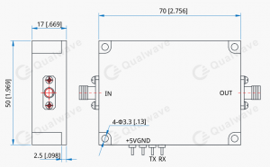
Unit: mm [in]
Tolerance: ±0.2mm [±0.008in]
4. How To Order
QFD6-0.001
Contact us for detailed specifications and sample support! As a leading supplier in high-frequency electronics, we specialize in the R&D and production of high-performance RF/microwave components, committed to delivering innovative solutions for global customers.
Post time: Sep-04-2025