 +86-28-6115-4929


RF coaxial termination is an important component in electronic circuits, usually used to connect to the end of coaxial cables, to absorb the energy of radio frequency (RF) or microwave signals and convert them into thermal energy. RF coaxial terminations are widely used in high-frequency applications such as radio communication, satellite communication, radar, and microwave communication. The following briefly introduces its characteristics and applications:
Characteristics:
1. The impedance of coaxial termination is usually 50 ohms, which matches the impedance of coaxial cables to minimize signal reflection and loss.
2. It can handle high-power RF and microwave signals, suitable for use in electronic devices and communication systems that require high power.
3. RF coaxial terminations are usually manufactured through precise processes, with high accuracy and stability.
4. High frequency coaxial terminations typically have a wide bandwidth and can cover multiple frequency ranges. This means that it can be used to process signals of various frequencies.
5. Suitable for applications with limited volume, such as micro circuits in microwave integrated circuits and satellite communication systems.
Applications:
1. Communication equipment testing: As a terminal load for vector network analyzers and signal generators, calibrate system impedance matching.
2. Radar and satellite systems: Absorb residual power from the transmission link and protect sensitive components from damage caused by reflected signals.
3. Laboratory research and development: Used for performance verification of power amplifiers, filters, and other devices to ensure the accuracy of test results.
Qualwave Inc. provide broadband and high power coaxial terminations cover the frequency range DC~110GHz. The average power handling is up to 2000 watts. The terminations are widely used in many applications. This article introduces a 30W coaxial termination with a working frequency of DC-12.4GHz.
1. Electrical Characteristics
Frequency Range: DC~12.4GHz
Average Power*1: 30W@25℃
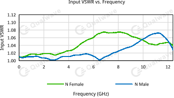
VSWR: 1.25 max.
Impedance: 50Ω
[1] Derated linearly to 1.5W@120°C.
Peak Power
| Peak Power (W) | Pulse Width (µS) | Duty Cycle (%) | Applicable Scope |
| 500 | 5 | 3 | @SMA,DC~12.4GHz |
| 5000 | 5 | 0.3 | @N,DC~12.4GHz |
VSWR
| Frequency (GHz) | VSWR (max.) |
| DC~4 | 1.20 |
| DC~4 | 1.25 |
| DC~12.4 | 1.25 |
2. Mechanical Properties
Connectors: N, SMA
3. Environment
Temperature: -55~+125℃
4. Outline Drawings
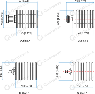
Unit: mm [in]
Tolerance: ±0.5mm [±0.02in]
5. Typical Performance Curves
6. How To Order
QCT1830-12.4-NF
If you are interested in this product, please feel free to contact us. We are happy to provide more valuable information. We support customization services for frequency range, connector types, and package dimensions.
Post time: Aug-07-2025