Features:
- Low VSWR
- Broadband
 +86-28-6115-4929
  sales@qualwave.com


The principle of mismatched termination is that when the impedance of the termination device does not match the impedance of the transmitter or receiver, a portion of the signal will be reflected back into the system, causing interference and loss in the signal transmission line.
1.Mis-matched terminations can cause some signals to be reflected back to the signal source, which can result in a loss of signal energy and power.
2. Mis-matched Loads can cause impedance mismatch between the signal source and the termination, which can result in mismatched output current and voltage of the signal transmission line.
3. Mismatched terminations will generate reflected waves on the transmission line, and the interaction between reflected waves and forward waves will generate interference and wave interference, affecting signal quality and system performance.
4. Mis-matched terminations can cause signal loss in the signal transmission line, which can affect the transmission distance and quality of the signal.
5. Mismatched loads can cause signal distortion, including amplitude distortion, phase distortion, frequency response distortion, etc.
6. Mis-matched Loads can cause energy loss in signal sources and transmission lines, resulting in thermal effects and affecting the stability and lifespan of the system.
1.Microwave mismatched terminations can cause a portion of energy to be reflected back to the signal source, resulting in a loss of signal power.
2.Causing noise and interference, multiple reflections of reflected waves on the transmission line may cause noise and interference.
3. Determine the frequency response of the signal. RF terminations can affect the frequency response of the signal, causing ripples in the frequency response.
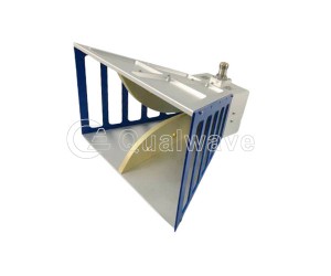
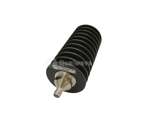
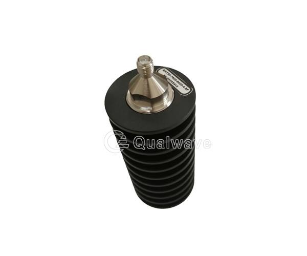
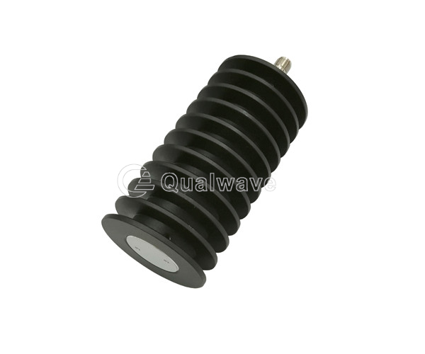
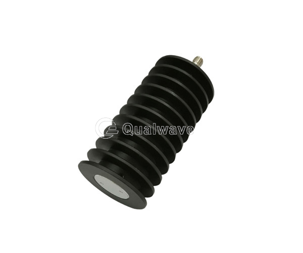
Qualwave supplies broadband and Low VSWR mismatch terminations cover the VSWR range 1~6. The average power handling is up to 1000 watts. The terminations are widely used in many aspects.

| Manually Variable Mismatch Terminations | |||||
|---|---|---|---|---|---|
| Part Number | Frequency (GHz) | Power (W) | VSWR (Max.) | Connectors | Lead Time (Weeks) |
| QMMTK1 | 0.85~2.17 | 100 | 1.2~5(Variable) | N | 0~4 |
| Broadband Mismatch Terminations | |||||
| Part Number | Frequency (GHz) | Power (W) | VSWR (Max.) | Connectors | Lead Time (Weeks) |
| QBMT50-1 | DC~8 | 50 | 3±0.3 | N | 0~4 |
| QBMT50 | 0.03~2.2 | 50 | 1~6(±7%) | N, SMA, 7/16 | 0~4 |
| QBMTK1 | 0.03~2.2 | 100 | 1~6(±7%) | N, SMA, 7/16 | 0~4 |
| QBMTK15 | 0.03~2.2 | 150 | 1~6(±7%) | N, SMA | 0~4 |
| QBMTK2 | 0.03~2.2 | 200 | 1~6(±7%) | N, SMA | 0~4 |
| QBMTK25 | 0.03~2.2 | 250 | 1~6(±7%) | N, SMA | 0~4 |
| QBMTK3 | 0.03~2.2 | 300 | 1~6(±7%) | N, SMA | 0~4 |
| QBMT50-2 | 0.1~0.715 | 50 | 4±0.3 | N | 0~4 |
| QBMT25 | 0.6~3.9 | 25 | 2.5±0.2 | SMA | 0~4 |
| QBMT30 | 0.6~3.9 | 30 | 3±0.5 | SMA | 0~4 |
| QBMTK1-1 | 1.6~2.8 | 100 | 4±0.4, 5±0.5, 6±0.6 | N | 0~4 |
| QBMTK2-1 | 9~10 | 200 | 1.5±0.3, 1.8±0.4, 2.0±0.4, 2.5±0.3, 3.0±0.5 | N | 0~4 |
| Narrow Band Mismatch Terminations | |||||
| Part Number | Frequency (GHz) | Power (W) | VSWR (Max.) | Connectors | Lead Time (Weeks) |
| QNMT02 | F0±5% (F0: 5 max.) | 2 | 1.5, 2, 2.5, 3, 3.5, 4, 4.5, 5 | N, SMA, BNC, TNC | 0~4 |
| QNMT50 | F0±5% (F0: 5 max.) | 50 | 1.5, 2, 2.5, 3, 3.5, 4, 4.5, 5 | N, SMA, BNC, TNC | 0~4 |
| QNMTK1 | F0±5% (F0: 5 max.) | 100 | 1.5, 2, 2.5, 3, 3.5, 4, 4.5, 5 | N, SMA, BNC, TNC | 0~4 |
| QNMTK15 | F0±5% (F0: 5 max.) | 150 | 1.5, 2, 2.5, 3, 3.5, 4, 4.5, 5 | N | 0~4 |
| QNMTK2 | F0±5% (F0: 5 max.) | 200 | 1.5, 2, 2.5, 3, 3.5, 4, 4.5, 5 | N | 0~4 |
| QNMTK25 | F0±5% (F0: 4 max.) | 250 | 1.5, 2, 2.5, 3, 3.5, 4, 4.5, 5 | N | 0~4 |
| QNMTK3 | F0±5% (F0: 4 max.) | 300 | 1.5, 2, 2.5, 3, 3.5, 4 | N | 0~4 |
| QNMTK4 | F0±5% (F0: 4 max.) | 400 | 1.5, 2, 2.5, 3, 3.5, 4 | N | 0~4 |
| QNMTK5 | F0±5% (F0: 4 max.) | 500 | 1.5, 2, 2.5, 3, 3.5, 4 | N | 0~4 |
| QNMTK8 | F0±5% (F0: 4 max.) | 800 | 1.5, 2, 2.5, 3, 3.5, 4 | N, 7/16, IF45 | 0~4 |
| QNMT1K | F0±5% (F0: 2 max.) | 1000 | 1.5, 2, 2.5, 3, 3.5, 4 | N, 7/16, IF45 | 0~4 |